MER-Service Training With Herb Knight, MER Service Manager

- Herb Knight And Student During Recent Service School

Service Training-
Glow Plugs
Having a hard time starting your diesel engine? It could be you have one or more failed glow plugs.
Everyone knows they have glow plugs and how to use them. What some don’t know is how a glow plug works or how to troubleshoot one. If you have to crank your diesel engine longer than you used to, on those cold mornings…..you may have a failed plug.

Figure 1 Parts of a Glow Plug
What does a glow plug do to help start your diesel engine? A glow plug actually heats the air in each individual cylinder. As a diesel engine does not have spark plugs to ignite the atomized diesel fuel being injected into each cylinder, it will utilize heat from compression to ignite the fuel. How does the compression in a diesel engine compare to…..let’s say you’re automobile. The average car engine has around a eight to one compression ratio. Those of you with the fancy sports car may reach nine to eleven to one compression ratio. The average Isuzu or /deere engine is between fifteen and twenty-two to one, and sometimes higher. The higher the compression ratio the higher the temperature of the air being compressed.

Figure 2 Testing
There are different types of glow plugs and air heaters. Today we are going to talk about the basic pen style plug as seen in the photos. Most all glow plugs work the same even though shaped differently; even the air heaters installed in the intake system of some of today’s newer diesel engines. To remove a glow plug for testing, spray the plug’s threads with penetrating oil. When you install glow plugs, always use a little Anti-Sieze compound on the threads

Figure 3 Bulging Tip
After reviewing the following pictures and text, if you have any questions on how to check your particular glow plugs or air heater, feel free to give me a call here at MER at 206-286-1817…..just ask for Herb.

Figure 4 It's All Over

Don’t Forget To Check Compression! I was recently debating with a customer about the importance of regular service and maintenance. He was adamant that valve adjustment was not that important on an engine that was already running good. So I made him a deal. I would adjust the valves, and if there was no difference in compression, the work performed was on the house. If there was a better than 10% difference, he would pay the bill.
We performed a cold cranking compression test with the following results:
Cylinder # Compression
1. 260
2. 360
3. 320
4. 400
5. 340
6. 280
We adjusted the valves then ran another compression test with the following results:
Cylinder # Compression
1. 320
2. 380
3. 370
4. 400
5. 370
6. 320
I’ll let you guess which cylinders had the tight valves, and which one was set correctly.
A cylinder with weak compression will change the way the cylinders fire. A weak cylinder will have late firing time and a weaker explosion in the cylinder. This will equate to lack of power and the dreaded “Excessive Fuel Consumption”.
Valves that are too tight do no close completely. This will have two effects. The first is carbon build up around the valve seat and face, which further interferes with the valves closing properly. The second is burnt valves. You will be able to determine that this has happened by the popping sound that comes out of the exhaust or intake.
The engine manufacturers have spent millions of dollars determining how to get the longest life out of your engine through proper maintenance. Do yourself a favor and follow the maintenance schedule. Like the old commercial said “You can pay me now or pay me later.” Herb Knight
MER Service Tip:
Avoid Hydraulic System Corrosion Out On Deck
Marine hydraulics out on deck are at increased risk of corrosion damage from the harsh environment.
Salt air, spray, & condensation are extremely hard on equipment, especially exposed pump and motor shafts–like on the crab block.
When the hydraulic system’s working, many of its components get warm. This drives moisture away from the metal surfaces but not the salt crystals left covering everything on deck. Heat only serves to concentrate the salt. When everything cools off, all those dry, salty surfaces draw moisture back like a sponge. An endless cycle: wind blowing across unprotected, salt-covered metal so oxidation–the dreaded corrosion–works with a vengeance. Add to that the different corrosion potential for some metals & you can have some serious corrosion to guard against.

Trouble Spots
Motor Shaft
A recently rediscovered innovation used by the Navy more than 50 years ago was designed to prevent corrosion on shafts exposed to weather. Grease dams keep air & water away from the area of the motor shaft that fails (Fig. 1), providing 100% protection when incorporated into the hydraulic motor’s mounting bracket.
Fittings
Preventing rust on fittings helps if you need to take them apart later. The best time to stop corrosion is before it starts–when installing new fittings. To stop rust on new or used plain-steel or cast-iron fittings try PetroWrap, a fairly weatherproof fabric tape impregnated with a tar-like substance (see box for metal options). First remove corrosion and thoroughly degrease fittings, then clean with a final rinse of acetone. Treat fittings with a rust neutralizer like Corroseal or Extend & let dry before wrapping all exposed metal. When using bronze or stainless you’ll pay more upfront but it takes less elbow grease to install and maintain. Stainless steel, however, is only stain-resistant, not stainproof, and some stainless steels will corrode.
Stainless bolts, fittings, & hardware fall into 2 general categories– magnetic or nonmagnetic– as determined by the alloys contained. Magnetic usually corrodes faster, but the chemical environment where the hardware’s used determines corrosion rate. Stainless-steel fittings, couplings, bolts & adapters are rated to help you get what you need for your application—i.e., a magnet attracts grade-304 stainless fittings (more iron) but not the higher-grade 316. In selecting your metal of choice for fittings also consider price and availability. Bronze now costs twice–and stainless 5 times–that of steel. Steel’s also “most” readily available while bronze & stainless tie for “least.”
The Deck Iron
The deck iron is made of aluminum, steel, or stainless steel and is mounted on-deck to connect the above and below-deck hydraulic systems. Hydraulic-oil passages through thedeck iron connect to various hydraulic
components out on deck. These couplings are exposed to the weather and should be protected. Once cleaned and primed, coat steel deck-irons with marine-grade paint like 2-part epoxy paint, but epoxy needs some warmth to cure quickly.
Hydraulic Controls
Most marine control valves originated in agricultural applications. They work well when new but are extremely prone to rust and corrosion that make the valve spool lock or stick. A spool valve that doesn’t spring back & return to center when releasing the handle is dangerous—it can kill people, even sink boats. Most control valves have cast-iron bodies and chrome-plated valve spools. A few valve makers do offer stainless spools–not always readily available but you can back-order if willing to wait. Rustproof control valves milled from a solid block of stainless steel are available in Norway, but pricey. Marine conversion kits for the more popular control valves are available. Kits contain bronze handles and stainless spools, end covers, links and pins. Look for the kit or complete control-valve assemblies with a special coating on the cast-iron valve body. It’s hard to coat a cast-iron body properly after the iron’s been oiled; however, the same rules for prepping steel also apply to cast iron.
Rust often locks valves because internal clearances between the valve body & spool are so small—only 0.0003” (3 ten-thousandths of an inch!) on a chromed valve spool & body, 0.0008” on stainless—tolerances way too close for most to make their own stainless-valve spools. Compared to chromed-steel spools the larger clearance for stainless allows for the greater expansion from its heat characteristics.
Like motor shafts on crab blocks, the trouble with control valves is the spool ends stick out into the world where rust and corrosion can wreak havoc on them and the pivots for their control linkage. “Rust wear” takes its toll–rusty pins get smaller, and the control action just gets worse and worse.
Hydraulic Remote Operated (HRO) valves are another option for dealing with rust. Mounted below deck to keep out of the weather, they’re still controlled from deck but by much smaller, less expensive valves–still at risk for rust but usually much easier to maintain than larger conventional valves. Fighting rust and corrosion’s a little like footprints in the sand, and then another wave washes over. It’s a constant battle, but your efforts are rewarded by ease of maintenance–and safe returns home.
Threads Review
All fittings, couplings, and adaptors fall into 2 broad categories: tapered or straight threads—always mated tapered to tapered, straight to straight. Tapered-Thread Fittings: (pipe-thread fittings, pipe fittings) come in plastic, aluminum, cast iron, steel, bronze, or stainless steel.Hydraulic hoses can have these crimped to both ends, or to one end with a straight-threaded coupling on the other. You must assemble tapered threads with thread sealant—use the right sealant for the metal, and always torque according to specs for pipe size. Every size of pipe has a torque specification; search for yours online or check with hydraulic shops. Straight-Thread Fittings: Crimp-on couplings can have straight threads and are available in steel, stainless steel, or bronze. Superior to tapered-thread couplings, they require no thread sealant & are easier to uncouple after years of use on deck.Before ordering a part be sure you know what you need, and you’ll be glad when you get the right part shipped PRIORITY FREIGHT—and it fits!
Engine Service Tip:
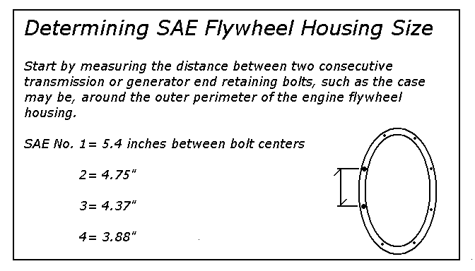
Always Verify Crankshaft Movement After Mounting Equipment To The Flywheel:

Engine driven equipment, such as generators can force the crankshaft hard against the thrust bearing, and destroy the engine! Measure the crankshaft movement, before and after mounting equipment to the flywheel to verify that the mounted equipment is not binding the crankshaft. The photo above shows where it is, inside the engine, that the crankshaft moves.
Introducing Another Important Subject-Visual Inspection and Pressure Testing:

Coolant Passages In Head Severly Plugged With Rust
Because all boaters have a big job to do in keeping up with maintenance, we have put together a primer on spotting defects in critical parts of the boat. We are also going to present the basics of pressure testing here today.
When beginning to inspect and test things, we soon learn that even brand-new, unused boat parts can have defects or cracks.
Visual inspection in good light is the starting point, and this includes the use of a magnifying glass, which like all test equipment, extends and multiplies the tester’s senses.
Remember to check the part in question with a couple of different methods before condemning it or using it. Whenever possible, verify visual findings with a pressure test.
Pressure Tests
Pressure testing is the process of learning whether a device that should hold pressure, or stop flow, will actually do it. There is also flow testing. With flow testing, it is possible to see if a device that is supposed to allow flow, does indeed let the flow through. Pressure and flow testing allows you to check areas in systems where visual inspection is impossible.
There are devices aboard boats that must always hold pressure, must sometimes hold pressure, must always allow flow, and must sometimes allow flow. For example, the engine water pump forces coolant through the cooling passages of the engine. The engine coolant thermostat must open and close at the right temperatures to either recirculate the coolant in the engine or to send it out to a heat exchanger for cooling. As previously mentioned, a flow test is simply verification that there is flow when and where it is needed. Compressed air, fuel, water, and coolant can all be used to verify flow visually.
Sometimes the fluid leaks will leave a trail you can track back to the source. One reason engines overheat is plugging of the cooling system with dissolved solids, which prevents
coolant flow. After an engine overheats, cracks develop in the engine castings and the coolant goes places it shouldn’t go. For example, coolant will flow from a cracked head or faulty head gasket into the engine cylinders, causing a hydraulic lock. Eventually, the coolant will reach the oil pan. It can also leak to the outside of the engine.
One simple pressure test involves blowing into a hollow fitting while plugging the other end with your thumb. If air leaks out from somewhere it shouldn’t, you’ve used a rudimentary form of pressure testing to locate the defect. This will work for testing many things, one example being engine vacuum controls. Marine gasoline engines have a vacuum advance diaphragm on the distributor that is easily tested with the mouth by pulling a vacuum on the diaphragm to see if it will hold a vacuum. You can also see if it will move the distributor linkage. When it’s important to keep away from the work piece for safety reasons, connect a piece of new or clean vacuum hose to the device you are testing. Most pressure testing is simply a variation of this method.
Next, consider a pressure leak. The tire on you boat trailer, with a slow leak, may first be checked audibly because leaks can often be heard. Stooping down by the tire and listening carefully may help locate the leak. If not, use a squirt bottle filled with diluted dish detergent to spray the tire, and watch for a foam “beard” over the leak.
If these methods don’t find the leak, the people at the tire shop will take it to the next level and place the tire in a tank of water and simply watch for bubbles. The same simple pressure tests used on a leaking tire will serve the boater well when a leak must be found.
Tools for Testing
The pressure gauge and the manometer are two of the most common pressure testing tools. Both take skill to use and to observe accurately. The range of pressure gauges varies widely. This is because a gauge that is used to check pressures in the 5,000 psi range won’t be sensitive enough for use in the range of 5 psi. Therefore, mechanics use whatever range of pressure gauge is right for the application.
In the above example where 5,000 psi is to be measured, a gauge of higher capacity would be used. A gauge with a range from zero to 6,000 psi would be used to provide a safety margin in case of an unexpected pressure spike. Likewise, to measure 5 psi, a 10 psi gauge would be suitable, or, as we’ll see, a manometer will very accurately measure low pressures, including vacuum readings.
Note: When pressure testing, be very careful to standardize the way you look at the pressure gauge. It also helps to close one eye and center the line-of-sight so that readings taken over time are consistent.
Manometers are made of transparent tubing and work something like a barometer. They register changes in pressure by the movement of a column of liquid contained inside the transparent tubing.
The advantage of the manometer is extreme accuracy. The pressure readings are taken in inches of water or inches of mercury. Both of these readings are easy to convert directly to psi or the metric unit of pressure, kilopascals (kPa). Notice the meniscus in the following drawing. Manometers filled with water display a curve shaped like a smile at the top of the water column. A mercury-filled manometer, on the other hand, displays a meniscus that is just the opposite, like a frown.
Cylinder Pressure Testing
The engine cylinder compression test is one of the most common. It uses a pressure gauge to register the maximum pressure that a cylinder will develop when the engine is cranked with the starter motor.
The test pressure gauge is installed in each cylinder, one at a time, and then the cylinder pressures are compared. The more uniform the cylinder pressures are, the better the engine will run. When a cylinder’s maximum pressure is less than 90 percent of the highest cylinder pressures, it is time to find the cause for the low cylinder’s pressure reading. Considering the way piston engines are built, the most common reasons for low cylinder pressure are a valve seat leak, a piston ring leak, or a hole in a piston. This testing method can leave the user with some uncertainty as to the cause of the low pressure. However, if the spark plug (gasoline engine) is fouled, it is safe to say the engine is burning a lot of oil and that the rings are involved.
If the plug is not fouled and the engine does not burn much oil, then the compression may be leaking away through a valve seat. Often, an intake valve seat leak can be checked audibly by listening in the air intake while the engine is running. Likewise, an exhaust leak can be checked by listening near the outlet of the exhaust pipe.
There is a better test for cylinder condition that takes a little more time, skill, and equipment. It is called the cylinder leak down test.
Cylinder Leak-Down Testing
Often used on aircraft engines, this method is very good for determining cylinder and valve condition. The testing is done after attaching the test apparatus to the spark plug hole (gasoline engine) or in the injector hole (diesel engine). This test must be done with the batteries disconnected to prevent accidental cranking of the engine. The leak-down test works by comparing the leakage rate of any cylinder against a known pressure and volume of air that is plumbed into the cylinder through the leak-down tester.
Exhaust Back-Pressure Testing
Exhaust back-pressure testing measures excess exhaust flow restriction of the engine. Engines run better with low back-pressure in the exhaust system. Generally speaking, exhaust back-pressure on gasoline and diesel engines must be less than four inches of mercury (1.5 psi), as measured with a manometer.
The manometer must only be connected in a straight section of pipe at least a foot away from the nearest bend in the exhaust plumbing. When there is no place to connect the manometer to the exhaust system, a small hole may be drilled that is suitable for tapping to a 1/8-inch normal temperature and pressure (NTP) pipe fitting size. This hole is plugged with a pipe plug after the test.
It is not enough to run the engine up to full speed in neutral to check for back-pressure. The engine must be used at full power under sea trial conditions for accurate results.
Note: Because elemental mercury is so much heavier than water, a manometer filled with mercury is capable of measuring much higher pressures than one filled with water.
Measuring the intake manifold pressure is also done with a manometer and is good for testing turbochargers.
The manometer works well for testing crankcase pressure too, and the test results are a good indication of the cylinder and piston condition. One sign of poor piston ring sealing is excessive blow-by of combustion gases past the piston rings. When the engine crankcase pressure gets too high, the engine will tend to leak oil. High crankcase pressure will also cause the front and rear crankcase seals to fail.
Text Excerpt from PRACTICAL BOAT MECHANICS by Ben Evridge, to be printed 7-09 by International Marine Publishing
Understanding MER Equipment Model Designations:

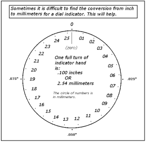
- Inches-to-metric Dial Indicator Conversion

This drawing will help convert metric dial indicator readings to inches.
The drawing below will aid in temperature conversions.
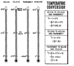
- Temperature Conversion Chart


Leave a comment